This design is based on the 18 Watt Audio Amplifier, and was developed mainly to satisfy the requests of correspondents unable to locate the TLE2141C chip. It uses the widespread NE5532 Dual IC but, obviously, its power output will be comprised in the 9.5 - 11.5W range, as the supply rails cannot exceed ±18V.
10 W Audio Amplifier Circuit Diagram
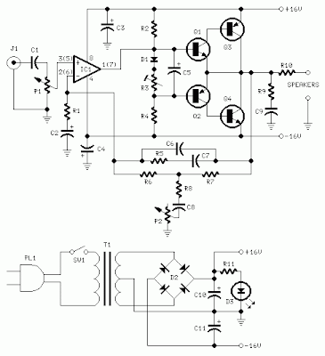
As amplifiers of this kind are frequently used to drive small loudspeaker cabinets, the bass frequency range is rather sacrificed. Therefore a bass-boost control was inserted in the feedback loop of the amplifier, in order to overcome this problem without quality losses. The bass lift curve can reach a maximum of +16.4dB @ 50Hz. In any case, even when the bass control is rotated fully counterclockwise, the amplifier frequency response shows a gentle raising curve: +0.8dB @ 400Hz, +4.7dB @ 100Hz and +6dB @ 50Hz (referred to 1KHz).
Notes:
- Can be directly connected to CD players, tuners and tape recorders.
- Schematic shows left channel only, but C3, C4, IC1 and the power supply are common to both channels.
- Numbers in parentheses show IC1 right channel pin connections.
- A log type for P2 will ensure a more linear regulation of bass-boost.
- Do not exceed 18 + 18V supply.
- Q3 and Q4 must be mounted on heatsink.
- D1 must be in thermal contact with Q1.
- Quiescent current (best measured with an Avo-meter in series with Q3 Emitter) is not critical.
- Set the volume control to the minimum and R3 to its minimum resistance.
- Power-on the circuit and adjust R3 to read a current drawing of about 20 to 25mA.
- Wait about 15 minutes, watch if the current is varying and readjust if necessary.
- A correct grounding is very important to eliminate hum and ground loops. Connect to the same point the ground sides of J1, P1, C2, C3 &C4. Connect C9 to the output ground.
- Then connect separately the input and output grounds to the power supply ground.
Parts:
P1_________________22K   Log.Potentiometer (Dual-gang for stereo)
P2________________100K   Log.Potentiometer (Dual-gang for stereo)
R1________________820R   1/4W Resistor
R2,R4,R8____________4K7  1/4W Resistors
R3________________500R   1/2W Trimmer Cermet
R5_________________82K   1/4W Resistor
R6,R7______________47K   1/4W Resistors
R9_________________10R   1/2W Resistor
R10__________________R22   4W Resistor (wirewound)

C1,C8_____________470nF   63V Polyester Capacitor
C2,C5_____________100µF   25V Electrolytic Capacitors
C3,C4_____________470µF   25V Electrolytic Capacitors
C6_________________47pF   63V Ceramic or Polystyrene Capacitor
C7_________________10nF   63V Polyester Capacitor
C9________________100nF   63V Polyester Capacitor

D1______________1N4148    75V 150mA Diode

IC1_____________NE5532    Low noise Dual Op-amp

Q1_______________BC547B   45V 100mA NPN Transistor
Q2_______________BC557B   45V 100mA PNP Transistor
Q3_______________TIP42A   60V 6A    PNP Transistor
Q4_______________TIP41A   60V 6A    NPN Transistor

J1__________________RCA audio input socket
Power supply parts:
R11_________________1K5  1/4W Resistor

C10,C11__________4700µF   25V Electrolytic Capacitors

D2________________100V 4A Diode bridge
D3________________5mm. Red LED

T1________________220V Primary, 12 + 12V Secondary 24-30VA Mains transformer

PL1_______________Male Mains plug

SW1_______________SPST Mains switch
Technical data:
- Output power:
- 10 Watt RMS into 8 Ohm (1KHz sinewave)
- Sensitivity:
- 115 to 180mV input for 10W output (depending on P2 control position)
- Frequency response:
- See Comments above
- Total harmonic distortion @ 1KHz:
- 0.1W 0.009% 1W 0.004% 10W 0.005%
- Total harmonic distortion @ 100Hz:
- 0.1W 0.009% 1W 0.007% 10W 0.012%
- Total harmonic distortion @ 10KHz:
- 0.1W 0.056% 1W 0.01% 10W 0.018%
- Total harmonic distortion @ 100Hz and full boost:
- 1W 0.015% 10W 0.03%
- Max. bass-boost referred to 1KHz:
- 400Hz = +5dB; 200Hz = +7.3dB; 100Hz = +12dB; 50Hz = +16.4dB; 30Hz = +13.3dB
- Unconditionally stable on capacitive loads


