This is a simple - easy to build - transistor based motorcycle alarm. Its designed to work at 12-volts. But - if you change the relay for one with a 6-volt coil - itll protect your "Classic Bike". The standby current is virtually zero - so it wont drain your battery.
Any number of normally-open switches may be used. Fit the mercury switches so that they close when the steering is moved or when the bike is lifted off its side-stand or pushed forward off its centre-stand. Use micro-switches to protect removable panels and the lids of panniers etc. While at least one switch remains closed - the siren will sound.
About one minute after all of the switches have been opened again - the alarm will reset. How long it takes to switch off depends on the characteristics of the actual parts youve used. You can adjust the time to suit your requirements by changing the value of C1 and/or R3. The circuit is designed to use an electronic Siren drawing 300 to 400mA.
Its not usually a good idea to use the bikes own Horn because it can be easily located and disconnected. However, if you choose to use the Horn, remember that the alarm relay is too small to carry the necessary current. Connect the coil of a suitably rated relay to the Siren output - and use its contacts to sound the horn. The circuit board and switches must be protected from the elements.
Dampness or condensation will cause malfunction. Without its terminal blocks, the board is small. Ideally, you should try to find a siren with enough spare space inside to accommodate it. Fit a 1-amp in-line fuse as close as possible to the power source. This is Very Important. The fuse is there to protect the wiring - not the circuit board.
Instead of using a key-switch you can use a hidden switch; or you could use the normally-closed contacts of a small relay. Wire the relay coil so that its energized while the ignition is on. Then every time you turn the ignition off - the alarm will set itself. When its not sounding, the circuit uses virtually no current. This should make it useful in other circumstances.
For example, powered by dry batteries and with the relay and siren voltages to suit, it could be fitted inside a computer or anything else thats in danger of being picked up and carried away. The low standby current and automatic reset means that for this sort of application an external on/off switch may not be necessary.
When you set the alarm - if one of the switches is closed - the siren will sound. This could cause annoyance late at night. A small modification will allow you to Monitor The State Of The Switches using LEDs. When the LEDs are all off - the switches are all open - and its safe to turn the alarm on.

Read More..
 |
| Simple Transistor Based Motorcycle Alarm |
About one minute after all of the switches have been opened again - the alarm will reset. How long it takes to switch off depends on the characteristics of the actual parts youve used. You can adjust the time to suit your requirements by changing the value of C1 and/or R3. The circuit is designed to use an electronic Siren drawing 300 to 400mA.
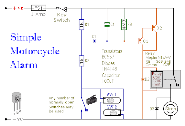 |
| Simple Transistor Based Motorcycle Alarm Circuit Diagram |
Dampness or condensation will cause malfunction. Without its terminal blocks, the board is small. Ideally, you should try to find a siren with enough spare space inside to accommodate it. Fit a 1-amp in-line fuse as close as possible to the power source. This is Very Important. The fuse is there to protect the wiring - not the circuit board.
Instead of using a key-switch you can use a hidden switch; or you could use the normally-closed contacts of a small relay. Wire the relay coil so that its energized while the ignition is on. Then every time you turn the ignition off - the alarm will set itself. When its not sounding, the circuit uses virtually no current. This should make it useful in other circumstances.
For example, powered by dry batteries and with the relay and siren voltages to suit, it could be fitted inside a computer or anything else thats in danger of being picked up and carried away. The low standby current and automatic reset means that for this sort of application an external on/off switch may not be necessary.
When you set the alarm - if one of the switches is closed - the siren will sound. This could cause annoyance late at night. A small modification will allow you to Monitor The State Of The Switches using LEDs. When the LEDs are all off - the switches are all open - and its safe to turn the alarm on.
Veroboard Layout
