Tuesday, February 4, 2014

12V to 20V Automotive Power Converter

 12V to +-20V Automotive Power Converter Diagram

12V to +-20V Automotive Power Converter (for audio amplifier)

The limitation of car supply voltage (12V) forces to convert the voltages to higher in order to power audio amplifiers. In fact the max audio power x speaker (with 4 ohm impedance) using 12V is (Vsupply+ - Vsupply-)^2/(8*impedance) 12^2/32 = 4.5Watts per channel, that is laughable... For powering correctly an amplifier the best is to use a symmetric supply with a high voltage differential. for example +20 - -20 = 40Volts in fact 40^2/32 = 50 Watts per channel that is respectable. This supply is intended for two channels with 50W max each (of course it depends on the amplifier used). Though it can be easily scaled up or the voltages changed to obtain different values.
Read More..

Saturday, January 11, 2014

After cell phone jammer has been used for several times

After cell phone jammer has been used for several times. 
Hybrid satellite and terrestrial solutions to the countries covered by geostationary satellites in low-power repeater network and the mobile base station co-location, to provide urban and indoor coverage. The manufacturers argue that, if you do not use the S-band in the country coverage of the DVB-H in UHF is not economical because it requires a large number of transmitter and receiver. The market is still before the analog shutdown mode, the lack of available digital spectrum to support deployment of this technology, at the same time, the S-band frequency bands are available in any place. Manufacturers are expected to DVB-SH will commence in Europe for land the citys commercial, the end of 2007 to 2009, there will be a dedicated satellite to provide country-wide coverage. The product description of cell phone jammer should be as exact and accurate as possible.
But each side is the lack of adequate dominant industry chain parties seems to be "co-operation", but in reality there are some differences in the distribution of benefits, rights and responsibilities, payment. Mobile payment, the killer application of the operators. Operators, mobile payment is different from the direct consumption of mobile phone ring tones, mobile games and other value-added services, it belongs to the node type, interface type of business, is the pay part of the new channels open up commercial activities. Therefore, mobile payment is similar to the "qigong" in the martial arts, its role is fundamental, permeability, promoting other business consumer. At the same time, although early in the development of mobile payment can not effectively bring commission income, but can bring some traffic income. The battery of cell phone jammer should be recharged for about five or six hours.
Moreover, as a strategy, trends, business, help to attract new customers, retain old users. Therefore, operators should seize the phone pay by 3G tendency to accelerate development opportunities, a clear development goals, integration of all resources, conditional step by step to carry out mobile payment services. The mobile payment operators to go from here. In general, operators should reshape the core position in the field of mobile payments, seize the commanding heights of mobile payment industrial chain. From the necessity, first, to avoid the pipeline: the bank or third-party mobile payment mode, the operator only as a SMS to confirm the authentication channel, failed to produce the brand in the customer interface.
Read More..

Friday, January 10, 2014

Up Down Timer For A Power Antenna

This up/down timer was designed to control a power antenna on a late-model vehicle. Normally, this vehicle uses a body computer to control the antenna. However, the person who owned the vehicle wanted to install his own high-powered audio stereo system. The original stereo system was tied in with the body computer and this meant that a separate antenna controller was required for the after-market sound system.

Also, the power antenna fitted did not have limit switches inside, hence the need for a timed control circuit. Heres how the circuit works. first, assume that the radio antenna control output is not switched on - ie, the radio is switched off. In that case, relay RLYC will be off and so relay RLYA will also be off, as is the motor. Conversely, when the radio is switched on, the radio antenna control output line switches to +12V.

And when that happens, RLYC closes its contacts and applies power to the circuit. As a result, C2 (330OF) quickly charges via D4, while Q4 is biased on via D5 and R5. This ensures that Q3 and relay RLYB remain off. At the same time, Q2 is is turned on, thus turning on RLYA and applying power to the motor. This drives the antenna in the up direction. During this time, C1 charges via R2.

Circuit diagram:

Up and down timer for a power antenna circuit schematic

When the voltage across the capacitor reaches +8.1V, Q1 turns on via ZD1 and so Q2 turns off and switches off the relay - ie, this gives the "up" timeout. Using the values shown for C1, R2 and ZD1 gives an "up" duration of approximately 6 seconds - long enough to fully extend the antenna. D1 discharges C1 (via resistor R1) when the +12V supply is later removed. When the radio is switched off (or a CD placed into the stereo unit), the radio antenna control output switches back to 0V.

This does several things: first, it turns Q4 off and this allows Q3 to turn on due to the stored charge in C2. Q3 and RLYB now turn on for about six seconds - ie, while C2 discharges via R4 - and this switches power to the motor in the opposite direction to drive the antenna down. Diodes D4 and D5 are there to prevent C2 from discharging back via the circuitry around on Q1 and Q2.

Author: Peter Howarth - Copyright: Silicon Chip Electronics
Read More..

Transistor Based Motorcycle Alarm

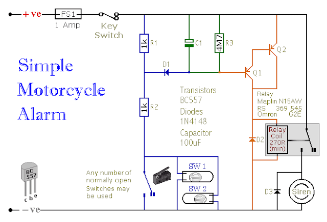
This is a simple - easy to build - transistor based motorcycle alarm. Its designed to work at 12-volts. But - if you change the relay for one with a 6-volt coil - itll protect your "Classic Bike". The standby current is virtually zero - so it wont drain your battery.

Simple Transistor Based Motorcycle Alarm
Any number of normally-open switches may be used. Fit the mercury switches so that they close when the steering is moved or when the bike is lifted off its side-stand or pushed forward off its centre-stand. Use micro-switches to protect removable panels and the lids of panniers etc. While at least one switch remains closed - the siren will sound.

About one minute after all of the switches have been opened again - the alarm will reset. How long it takes to switch off depends on the characteristics of the actual parts youve used. You can adjust the time to suit your requirements by changing the value of C1 and/or R3. The circuit is designed to use an electronic Siren drawing 300 to 400mA.

Simple Transistor Based Motorcycle Alarm
Simple Transistor Based Motorcycle Alarm Circuit Diagram
Its not usually a good idea to use the bikes own Horn because it can be easily located and disconnected. However, if you choose to use the Horn, remember that the alarm relay is too small to carry the necessary current. Connect the coil of a suitably rated relay to the Siren output - and use its contacts to sound the horn. The circuit board and switches must be protected from the elements.

Dampness or condensation will cause malfunction. Without its terminal blocks, the board is small. Ideally, you should try to find a siren with enough spare space inside to accommodate it. Fit a 1-amp in-line fuse as close as possible to the power source. This is Very Important. The fuse is there to protect the wiring - not the circuit board.

Instead of using a key-switch you can use a hidden switch; or you could use the normally-closed contacts of a small relay. Wire the relay coil so that its energized while the ignition is on. Then every time you turn the ignition off - the alarm will set itself. When its not sounding, the circuit uses virtually no current. This should make it useful in other circumstances.

For example, powered by dry batteries and with the relay and siren voltages to suit, it could be fitted inside a computer or anything else thats in danger of being picked up and carried away. The low standby current and automatic reset means that for this sort of application an external on/off switch may not be necessary.

When you set the alarm - if one of the switches is closed - the siren will sound. This could cause annoyance late at night. A small modification will allow you to Monitor The State Of The Switches using LEDs. When the LEDs are all off - the switches are all open - and its safe to turn the alarm on.

Veroboard Layout


Simple Transistor Based Motorcycle Alarm

Read More..