Tuesday, February 4, 2014
12V to 20V Automotive Power Converter
Friday, January 10, 2014
Up Down Timer For A Power Antenna
Also, the power antenna fitted did not have limit switches inside, hence the need for a timed control circuit. Heres how the circuit works. first, assume that the radio antenna control output is not switched on - ie, the radio is switched off. In that case, relay RLYC will be off and so relay RLYA will also be off, as is the motor. Conversely, when the radio is switched on, the radio antenna control output line switches to +12V.
And when that happens, RLYC closes its contacts and applies power to the circuit. As a result, C2 (330OF) quickly charges via D4, while Q4 is biased on via D5 and R5. This ensures that Q3 and relay RLYB remain off. At the same time, Q2 is is turned on, thus turning on RLYA and applying power to the motor. This drives the antenna in the up direction. During this time, C1 charges via R2.
Circuit diagram:

When the voltage across the capacitor reaches +8.1V, Q1 turns on via ZD1 and so Q2 turns off and switches off the relay - ie, this gives the "up" timeout. Using the values shown for C1, R2 and ZD1 gives an "up" duration of approximately 6 seconds - long enough to fully extend the antenna. D1 discharges C1 (via resistor R1) when the +12V supply is later removed. When the radio is switched off (or a CD placed into the stereo unit), the radio antenna control output switches back to 0V.
This does several things: first, it turns Q4 off and this allows Q3 to turn on due to the stored charge in C2. Q3 and RLYB now turn on for about six seconds - ie, while C2 discharges via R4 - and this switches power to the motor in the opposite direction to drive the antenna down. Diodes D4 and D5 are there to prevent C2 from discharging back via the circuitry around on Q1 and Q2.
Tuesday, December 24, 2013
Simple Low Power Car Stereo Amplifier
A simple low power car stereo amplifier circuit based on TDA 2003 is shown here. The circuit uses cheap, readily available components and it is very easy to construct. TDA2003 is an integrated car radio amplifier from ST Micro electronics that has a lot of good features like short circuit protection for all pins, thermal over range low harmonic distortion, low cross over distortion etc.
Circuit diagram :
A simple low power car stereo amplifier Circuit Diagram
In the circuit given here each TDA2003 is wired as a mono amplifier operating from a 12V supply. Resistors R2 and R3 forms a feedback network that sets the amplifiers gain. C7 is the input DC de-coupling capacitor and C5 couples the speaker to the amplifiers output. C4 is used for improving the ripple rejection while C1 and C2 are employed for power supply filtering. C3 and R1 are used for setting the upper frequency cut-off. Network comprising of C6 and R4 is used for frequency stabilization and to prevent oscillation.
Notes.
- Assemble the circuit on a good quality PCB.
- Heat sinks are necessary for both ICs.
- The circuit can be operated from 12V DC.
- S1 is the ON/OFF switch
Tuesday, October 1, 2013
Power Buzzer
The power quickly drops as the supply voltage decreases (P = Urms 2 / RL). The power supply for this circuit is not particularly critical. However, it must be able to provide sufficient current. A good nominal value is around 400 mA at 20 V. At 4 V, it will be approximately 25 mA. Most likely, you can find a suitable power supply somewhere in your hobby room. Otherwise, you can certainly find a low-cost power supply design in our circuits archive that will fill the bill!
Tuesday, September 24, 2013
Power Buzzer Circuit
How often on average do you have to call members of your family each day to tell them that dinner is ready, it’s time to leave, and the like? The person you want is usually in a different room, such as the hobby room or bedroom. A powerful buzzer in the room, combined with a pushbutton at the bottom of the stairs or in the kitchen, could be very handy in such situations. The heart of this circuit is formed by IC1, a TDA2030. This IC has built-in thermal protection, so it’s not likely to quickly give up the ghost. R1 and R2 apply a voltage equal to half the supply voltage to the plus input of the opamp. R3 provides positive feedback. Finally, the combination of C2, R4 and trimmer P12 determines the oscillation frequency of the circuit.
The frequency of the tone can also be adjusted using P1. There is no volume control, since you always want to get attention when you press pushbutton S1. Fit the entire circuit where you want to have the pushbutton. The loudspeaker can then be placed in a strategic location, such as in the bedroom or wherever is appropriate. Use speaker cable to connect the loudspeaker. Normal bell wire can cause a significant power loss if the loudspeaker is relatively far away. The loudspeaker must be able to handle a continuous power of at least 6 W (with a 20-V supply voltage).
The power quickly drops as the supply voltage decreases (P = Urms 2 / RL). The power supply for this circuit is not particularly critical. However, it must be able to provide sufficient current. A good nominal value is around 400 mA at 20 V. At 4 V, it will be approximately 25 mA. Most likely, you can find a suitable power supply somewhere in your hobby room. Otherwise, you can certainly find a low-cost power supply design in our circuits archive that will fill the bill!
Author: G. Baars
Copyright: Elektor Electronics
Wednesday, June 5, 2013
Electrical Floorplans Power Voltage Structured Wiring
Have Separate Wiring To Carry Energy Loads To And From The House.
Electrical Floorplans With Power Low Voltage And Structured Wiring.
How To Connect Home Electrical Wiring From A House Panel To A Garage.
Electrical Goods Equipment Supplies Precision Electricals House Wiring.
Or Residential Home With Basic Electrical Wiring And Hvac Complete.
House Electric Wiring Diagram Home Branch Circuits Home Electrical.

Electrical Wiring For Homes Is The Use Of Insulated Conductors And.
Way Switch Wiring Diagram Variation 3 Electrical Online.
Electrical Wiring Diagram Bathroom.
250 And 525 Sx Mxc Exc Electrical System And Wiring Diagram Here.
Tuesday, June 4, 2013
Power Coming Switch Lights Series
Com Wp Content Uploads 2008 01 2 Way Switch Wiring Diagram Jpg.
Way Switch Feed To Switch Alternate Method Standard Receptacle.
Humbuckers 3 Way Toggle Switch With 1 Volume Guitar Wiring Diagram.
Wiring This Is The Correct Wiring For 3 Way Selector.
Is Basically A 3 Way Circuit With A 4 Way Switch Added Between The 2.
Video Animation Dc Three Way Switch Showing Current Flow By Russell.
Option 2 Power To Switch To Switch To Light To Light.
Toyota Fj Cruiser Brake Switch Wiring Diagram Circuit Schematic.
Power Coming In At Switch With 2 Lights In Series.
Work Let S Say That Switch 1 Is At The Bottom Of A Stairway And Switch.
Friday, April 12, 2013
Variable Voltage and Current Power Supply Circuit Using LM1458

The operation of this circuit is the power transformer requires an additional winding to supply the op-amps with a bipolar voltage (+/- 8 volts), and the negative voltage is also used to generate a reference voltage below ground so that the output voltage can be adjusted all the way down to 0. Current limiting is accomplished by sensing the voltage drop across a small resistor placed in series with the negative supply line. As the current increases, the voltage at the wiper of the 500 ohm pot rises until it becomes equal or slightly more positive than the voltage at the (+) input of the op amp.
Current limiting range is about 0 - 3 amps with components shown. The TIP32 and 2N3055 pass transistors should be mounted on suitable heat sinks and the 0.2 ohm current sensing resistor should be rated at 2 watts or more. The op amp output then moves negative and reduces the voltage at the base of the 2N3053 transistor which in turn reduces the current to the 2N3055 pass transistor so that the current stays at a constant level even if the supply is shorted. The heat produced by the pass transistor will be the product of the difference in voltage between the input and output, and the load current.
Variable DC Power Supply Rise
An LED has been put in to the output of the fixed 5V regulator to point that the circuit is working. Poor soldering is the in all probability purpose that the circuit does not work. Check that the entire soldering is finished properly. Check that all sections are within their proper position on the PCB. Other items to take a seem to be at are to make sure that the regulators, electrolytic capacitor & bridge rectifier are inserted in the right orientation.
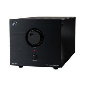
150W Power Amplifier Dayton Audio APA150

Technical Details :
- close to clamor-released fan process pro approach handle applications
- silky enlightened design looks useful in vogue every audio practice
- sky-scraping current, discrete output transistors with the purpose of run cool and serene
- adaptable 50-150 Hz low pass crossover gives you the area control you need
Thursday, April 11, 2013
PRECISION POWER REGULATOR ELECTRONIC DIAGRAM
A precision voltage source is quite easy, except when the voltage should be consistent over wide range of ambient temperature. This requirement might be needed in high precision measurement system environment. For example, to provide reference voltage in analog to digital conversion.
Subwoofer amplifier with 30W output power


C3 = 47uF
C4 = 100nF
C5 = 10uF
C6 = 47uF
C7 = 100uF
IC = SI1020GL , SI1030G
Wednesday, April 10, 2013
Low Power FM Transmitter
NOTE: A few people have had trouble with this circuit. The biggest problem is not knowing if it is even oscillating, since the frequency is outside the range of most simple oscilloscopes. See Project 74 for a simple RF probe that will (or should) tell you that you have a useful signal at the antenna. If so, then you know it oscillates, and just have to find out at what frequency. This may require the use of an RF frequency counter if you just cannot locate the FM band.
Description
The circuit of the transmitter is shown in Figure 1, and as you can see it is quite simple. The first stage is the oscillator, and is tuned with the variable capacitor. Select an unused frequency, and carefully adjust C3 until the background noise stops (you have to disable the FM receivers mute circuit to hear this).
Figure 1 - Low Power FM TransmitterBecause the trimmer cap is very sensitive, make the final frequency adjustment on the receiver. When assembling the circuit, make sure the rotor of C3 is connected to the +9V supply. This ensures that there will be minimal frequency disturbance when the screwdriver touches the adjustment shaft. You can use a small piece of non copper-clad circuit board to make a screwdriver - this will not alter the frequency.
The frequency stability is improved considerably by adding a capacitor from the base of Q1 to ground. This ensures that the transistor operates in true common base at RF. A value of 1nF (ceramic) as shown is suitable, and will also limit the HF response to 15 kHz - this is a benefit for a simple circuit like this, and even commercial FM is usually limited to a 15kHz bandwidth.
Capacitors
All capacitors must be ceramic (with the exception of C1, see below), with C2 and C6 preferably being N750 (Negative temperature coefficient, 750 parts per million per degree Celsius). The others should be NPO types, since temperature correction is not needed (nor is it desirable). If you cannot get N750 caps, dont worry too much, the frequency stability of the circuit is not that good anyway (as with all simple transmitters).
How It Works
Q1 is the oscillator, and is a conventional Colpitts design. L1 and C3 (in parallel with C2) tunes the circuit to the desired frequency, and the output (from the emitter of Q1) is fed to the buffer and amplifier Q2. This isolates the antenna from the oscillator giving much better frequency stability, as well as providing considerable extra gain. L2 and C6 form a tuned collector load, and C7 helps to further isolate the circuit from the antenna, as well as preventing any possibility of short circuits should the antenna contact the grounded metal case that would normally be used for the complete transmitter.
The audio signal applied to the base of Q1 causes the frequency to change, as the transistors collector current is modulated by the audio. This provides the frequency modulation (FM) that can be received on any standard FM band receiver. The audio input must be kept to a maximum of about 100mV, although this will vary somewhat from one unit to the next. Higher levels will cause the deviation (the maximum frequency shift) to exceed the limits in the receiver - usually ±75kHz.
With the value shown for C1, this limits the lower frequency response to about 50Hz (based only on R1, which is somewhat pessimistic) - if you need to go lower than this, then use a 1uF cap instead, which will allow a response down to at least 15Hz. C1 may be polyester or mylar, or a 1uF electrolytic may be used, either bipolar or polarised. If polarised, the positive terminal must connect to the 10k resistor.
Inductors
The inductors are nominally 10 turns (actually 9.5) of 1mm diameter enamelled copper wire. They are close wound on a 3mm diameter former, which is removed after the coils are wound. Carefully scrape away the enamel where the coil ends will go through the board - all the enamel must be removed to ensure good contact. Figure 2 shows a detail drawing of a coil. The coils should be mounted about 2mm above the board.
For those still stuck in the dark ages with imperial measurements (grin), 1mm is about 0.04" (0.0394") or 5/127 inch (chuckle) - you will have to work out what gauge that is, depending on which wire gauge system you use (there are several). You can see the benefits of metric already, cant you? To work out the other measurements, 1" = 25.4mm
NOTE: The inductors are critical, and must be wound exactly as described, or the frequency will be wrong.
Figure 2 - Detail Of L1 And L2The nominal (and very approximate) inductance for the coils is about 130nH.This is calculated according to the formula ...
L = N² * r² / (228r + 254l)
... where L = inductance in microhenries (uH), N = number of turns, r = average coil radius (2.0mm for the coil as shown), and l = coil length. All dimensions are in millimetres.
Pre-Emphasis
It is normal with FM transmission that "pre-emphasis" is used, and there is a corresponding amount of de-emphasis at the receiver. There are two standards (of course) - most of the world uses a 50us time constant, and the US uses 75us. These time constants represent a frequency of 3183Hz and 2122Hz respectively. This is the 3dB point of a simple filter that boosts the high frequencies on transmission and cuts the same highs again on reception, restoring the frequency response to normal, and reducing noise.
The simple transmitter above does not have this built in, so it can be added to the microphone preamp or line stage buffer circuit. These are both shown in Figure 3, and are of much higher quality than the standard offerings in most other designs.
Figure 3 - Mic And Line PreampsRather than a simple single transistor amp, using a TL061 opamp gives much better distortion figures, and a more predictable output impedance to the transmitter. If you want to use a dynamic microphone, leave out R1 (5.6k) since this is only needed to power an electret mic insert. The gain control (for either circuit) can be an internal preset, or a normal pot to allow adjustment to the maximum level without distortion with different signal sources. The 100nF bypass capacitors must be ceramic types, because of the frequency. Note that although a TL072 might work, they are not designed to operate at the low supply voltage used. The TL061 is specifically designed for low power operation.
The mic preamp has a maximum gain of 22, giving a microphone sensitivity of around 5mV. The line preamp has a gain of unity, so maximum input sensitivity is 100mV. Select the appropriate capacitor value for pre-emphasis as shown in Figure 3 depending on where you live. The pre-emphasis is not especially accurate, but will be quite good enough for the sorts of uses that a low power FM transmitter will be put to. Needless to say, this does not include "bugging" of rooms, as this is illegal almost everywhere.
I would advise that the preamp be in its own small sub-enclosure to prevent RF from entering the opamp input. This does not need to be anything fancy, and you could even just wrap some insulation around the preamp then just wrap the entire preamp unit in aluminum foil. Remember to make a good earth connection to the foil, or the shielding will serve no purpose.
Tuesday, April 9, 2013
Low Power 12V Transformerless Power Supply
This means that it is usually not possible to use this sort of supply to drive a triac, which normally needs such a connection. However, circuits that employ relays can benefit from full-wave rectification. The value of the supply voltage depends on the specifications of the Zener diodes that are used, which can be freely chosen. C2 must be able to handle at least this voltage. The amount of current that can be delivered depends on the capacitance of C1. With the given value of 220nF, the current is approximately 15mA. A final warning: this sort of circuit is directly connected to mains voltage, which can be lethal. You must never come in contact with this circuit! It is essential to house this circuit safely in a suitable enclosure.
Monday, April 8, 2013
Power amplifier for FM radio receiver
Schematic
is suitable for use in radio tuner or FM radio receiver when it is
assembled and ready for use. Where if the low gear power radio receiver,
with the aid of power amplifier is less powerfull voice / hard to
better and just right. For use hios speakers , use a low-power ,
because power amplifier has only the power output of 2 X 5 Watt stereo
power amplifeir with impedance of 4 Ohm. Working on a minimum voltage of
4.5 Volts and maximum of 16Volt. Use the correct voltage supply -
really have been filtered out in order to improve the performance of
these power amplifiers.

Resistor
R1________180R
R2________180R
R3________18K
R4________18K
Capacitor
C1________47uF
C2________4.7uF
C4________100uF
C5________100uF
C6________47uF
C7________4.7uF
C8________47uF
C9________100uF
C10_______100uF
C11_______1000uF
C12_______1000uF
C13_______100pF
C14_______100pF
C15_______68n
C16_______68n
IC
IC1_______TA7215P
Sunday, April 7, 2013
Audio Amp Output Power Limiter Circuit

The operation of the circuit is a 10k resistor selected for the input, and although this is lower than I would like, many power amps have a relatively low input impedance and too much signal would be lost. The LDR simply shunts the signal to earth when it is illuminated. A single unit should control both channels of the power amp as shown. If only one channel is needed, then delete the components for "Right", including the associated light pipe.
The value of R3 must be selected based on the amplifier power. For a 100W amp, a value of 1.8k is about right, but it is likely that a little experimentation will be needed. As a rough guide, the table below will be helpful, and it is probable that the value from the table will be OK. The idea is to limit the current through the LED to a sensible maximum.
LM7812 using to 12V 30A Power Supply
This project design is using a single 7812 IC voltage regulator and multiple outboard pass transistors, this power supply can deliver output load currents of up to 30 amps. The design figure is in the below;

The input transformer is likely to be the most expensive part of the entire project. As an alternative, a couple of 12 Volt car batteries could be used. The input voltage to the regulator must be at least several volts higher than the output voltage (12V) so that the regulator can maintain its output. If a transformer is used, then the rectifier diodes must be capable of passing a very high peak forward current, typically 100amps or more. The 7812 IC will only pass 1 amp or less of the output current, the remainder being supplied by the outboard pass transistors. As the circuit is designed to handle loads of up to 30 amps, then six TIP2955 are wired in parallel to meet this demand. The dissipation in each power transistor is one sixth of the total load, but adequate heat sinking is still required. Maximum load current will generate maximum dissipation, so a very large heat sink is required. In considering a heat sink, it may be a good idea to look for either a fan or water cooled heat sink. In the event that the power transistors should fail, then the regulator would have to supply full load current and would fail with catastrophic results. A 1 amp fuse in the regulators output prevents a safeguard. The 400mohm load is for test purposes only and should not be included in the final circuit.
200W Stereo High Power Amplifier LM3886
The LM3886 circuit is in a non-inverted configuration, so the input impedance is determined by the input resistor R1, i.e. 47k. The 680 ohm and 470pF resistor capacitor filter network is used to filter out the high frequency noise at the RCA input. The 220pF C4 and C8 capacitors are used to shot out the high frequency noise at the LM3886 input pins.![]() |
| LM3886 Power Amplifier Schematics |
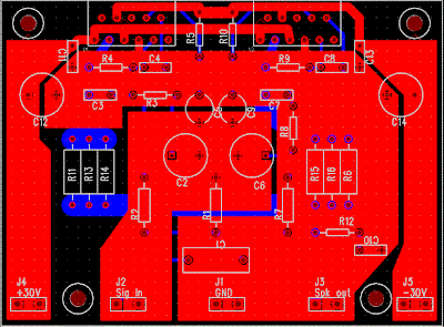
The PCB is designed in a way that the power ground is separated from the signal ground, as you can see from the below layout. The signal ground is located in the middle and surrounded by the power ground. There is a thin trace near C5 connecting them. The PCB layout is done by using PADS PowerPCB 5.0. I think it is a powerful layout software.
Amplifier Printed Circuit Board (PCB)
![]() |
| Amplifier Printed Circuit Board Bottom |
![]() |
| Amplifier Printed Circuit Board Top |
![]() |
| Amplifier Printed Circuit Board |
The power supply used is a regulated power supply. I used 10000uF per rail before the LT1083 regulator. After the regulator, I have 100uF on the regulator board. The advantage of using regulator is that the power supply ripple voltage is removed. If power regulation is not used, I can hear very little 50/100Hz hum from the speaker.
The high current MUR860 diode is used to ensure high current flow. The voltage regulator used is LT1083, it can provide about 8A of current. Transformer used here is a 500VA 2x 25V. The power supply is then regulated by 2 LT1083, after the regulation, the voltage is 30V.
![]() |
| Power Supply Recomended |
The sound of this amplifier is similar to my LM3875 amplifier, which is very clean and detail. It has no hum, no hiss and no noise. Compared to the LM3875 Gainclone, this amp can deliver twice the power to my 4-ohm speaker, and it improves the dynamics and bass punch a lot.
Source :http://www.shine7.com/audio/pa100.htm
Dual Power Supply Circuits
![]() |
| Click to view larger |
Saturday, April 6, 2013
Adapter power supply and charger circuit
![]() |
| Adapter, power supply and charger circuit |