Well the short version. The object is to get the cell voltage high enough for the sulphate to dissolve without boiling or melting the battery. This is achieved by applying higher voltage for shorter periods and let the battery rest for a while. The pulses on short range is about 0.5s on / 3s off and the long pulse range is 1.4s on / 2s off. These times can vary depending on component tolerances. Start on long pulse and if you discover “boiling” (more than with normal charging) in the electrolyte switch to short puls. Don’t leave the process unattended, at least until you know how your specific version of this project turns out. I built ver.1 of this circuit some 10 years ago and have experimented with it but I’m sure someone can improve it further.
Friday, December 27, 2013
Build a Pulse Charger for reviving tired Lead Acid batteries
Well the short version. The object is to get the cell voltage high enough for the sulphate to dissolve without boiling or melting the battery. This is achieved by applying higher voltage for shorter periods and let the battery rest for a while. The pulses on short range is about 0.5s on / 3s off and the long pulse range is 1.4s on / 2s off. These times can vary depending on component tolerances. Start on long pulse and if you discover “boiling” (more than with normal charging) in the electrolyte switch to short puls. Don’t leave the process unattended, at least until you know how your specific version of this project turns out. I built ver.1 of this circuit some 10 years ago and have experimented with it but I’m sure someone can improve it further.
Thursday, December 26, 2013
Touch Switch II
Wednesday, December 25, 2013
Build a Single cell Charger Circuit Diagram
Tuesday, December 24, 2013
Simple Low Power Car Stereo Amplifier
A simple low power car stereo amplifier circuit based on TDA 2003 is shown here. The circuit uses cheap, readily available components and it is very easy to construct. TDA2003 is an integrated car radio amplifier from ST Micro electronics that has a lot of good features like short circuit protection for all pins, thermal over range low harmonic distortion, low cross over distortion etc.
Circuit diagram :
A simple low power car stereo amplifier Circuit Diagram
In the circuit given here each TDA2003 is wired as a mono amplifier operating from a 12V supply. Resistors R2 and R3 forms a feedback network that sets the amplifiers gain. C7 is the input DC de-coupling capacitor and C5 couples the speaker to the amplifiers output. C4 is used for improving the ripple rejection while C1 and C2 are employed for power supply filtering. C3 and R1 are used for setting the upper frequency cut-off. Network comprising of C6 and R4 is used for frequency stabilization and to prevent oscillation.
Notes.
- Assemble the circuit on a good quality PCB.
- Heat sinks are necessary for both ICs.
- The circuit can be operated from 12V DC.
- S1 is the ON/OFF switch
Monday, December 23, 2013
Cheap 12V to 220V Inverter
These drive a 230 V to 2 × 9 V center-tapped transformer used ‘backwards’ to produce the 230 V output. The presence of the 230 VAC voltage is indicated by a neon light, while a VDR (voltage dependent resistor) type S10K250 or S07K250 clips off the spikes and surges that may appear at the transistor switching points. The output signal this circuit produces is approximately a square wave; only approximately, since it is somewhat distorted by passing through the transformer. Fortunately, it is suitable for the majority of electrical devices it is capable of supplying, whether they be light bulbs, small motors, or power supplies for electronic devices.
PCB layout:
Parts List :
Resistors
R1 = 18k?
R2 = 3k3
R3 = 1k
R4,R5 = 1k?5
R6 = VDR S10K250 (or S07K250)
P1 = 100 k potentiometer
Capacitors
C1 = 330nF
C2 = 1000 µF 25V
Semiconductor
T1,T2 = MJ3001
IC1 = 555
IC2 = 4013
Miscellaneous
LA1 = neon light 230 V
F1 = fuse, 5A
TR1 = mains transformer, 2x9V 40VA (see text)
4 solder pins
Note that, even though the circuit is intended and designed for powering by a car battery, i.e. from 12 V, the transformer is specified with a 9 V primary. But at full power you need to allow for a voltage drop of around 3 V between the collector and emitter of the power transistors. This relatively high saturation voltage is in fact a ‘shortcoming’ common to all devices in Darlington configuration, which actually consists of two transistors in one case. We’re suggesting a PCB design to make it easy to construct this project; as the component overlay shows, the PCB only carries the low-power, low-voltage components.
The Darlington transistors should be fitted onto a finned anodized aluminum heat-sink using the standard insulating accessories of mica washers and shouldered washers, as their collectors are connected to the metal cans and would otherwise be short-circuited. An output power of 30 VA implies a current consumption of the order of 3 A from the 12 V battery at the ‘primary side’. So the wires connecting the collectors of the MJ3001s [1] T1 and T2 to the transformer primary, the emitters of T1 and T2 to the battery negative terminal, and the battery positive terminal to the transformer primary will need to have a minimum cross-sectional area of 2 mm2 so as to minimize voltage drop.
The transformer can be any 230 V to 2 × 9 V type, with an E/I iron core or toroidal, rated at around 40 VA. Properly constructed on the board shown here, the circuit should work at once, the only adjustment being to set the output to a frequency of 50 Hz with P1. You should keep in minds that the frequency stability of the 555 is fairly poor by today’s standards, so you shouldn’t rely on it to drive your radio-alarm correctly – but is such a device very useful or indeed desirable to have on holiday anyway? Watch out too for the fact that the output voltage of this inverter is just as dangerous as the mains from your domestic power sockets.
So you need to apply just the same safety rules! Also, the project should be enclosed in a sturdy ABS or diecast so no parts can be touched while in operation. The circuit should not be too difficult to adapt to other mains voltages or frequencies, for example 110 V, 115 V or 127 V, 60 Hz. The AC voltage requires a transformer with a different primary voltage (which here becomes the secondary), and the frequency, some adjusting of P1 and possibly minor changes to the values of timing components R1 and C1 on the 555.
Sunday, December 22, 2013
Animal Friendiy Mousetrap
Animal Friendiy Mousetrap Circuit Diagram
The reset button has to be pressed to ready the trap for its next victim. The author has managed to catch a few dozen mice with this device. The program is written in PICBASIC Pro and can be freely downloaded from the Elektor website, it is found in archive file # 100308-11.zip.
Saturday, December 21, 2013
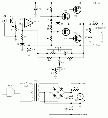
10 W Audio Amplifier Rise
As amplifiers of this kind are frequently used to drive small loudspeaker cabinets, the bass frequency range is rather sacrificed. Therefore a bass-boost control was inserted in the feedback loop of the amplifier, in order to overcome this problem without quality losses. The bass lift curve can reach a maximum of +16.4dB @ 50Hz. In any case, even when the bass control is rotated fully counterclockwise, the amplifier frequency response shows a gentle raising curve: +0.8dB @ 400Hz, +4.7dB @ 100Hz and +6dB @ 50Hz (referred to 1KHz).
Notes:
- Can be directly connected to CD players, tuners and tape recorders.
- Schematic shows left channel only, but C3, C4, IC1 and the power supply are common to both channels.
- Numbers in parentheses show IC1 right channel pin connections.
- A log type for P2 will ensure a more linear regulation of bass-boost.
- Do not exceed 18 + 18V supply.
- Q3 and Q4 must be mounted on heatsink.
- D1 must be in thermal contact with Q1.
- Quiescent current (best measured with an Avo-meter in series with Q3 Emitter) is not critical.
- Set the volume control to the minimum and R3 to its minimum resistance.
- Power-on the circuit and adjust R3 to read a current drawing of about 20 to 25mA.
- Wait about 15 minutes, watch if the current is varying and readjust if necessary.
- A correct grounding is very important to eliminate hum and ground loops. Connect to the same point the ground sides of J1, P1, C2, C3 &C4. Connect C9 to the output ground.
- Then connect separately the input and output grounds to the power supply ground.
Parts:
P1_________________22K Log.Potentiometer (Dual-gang for stereo)
P2________________100K Log.Potentiometer (Dual-gang for stereo)
R1________________820R 1/4W Resistor
R2,R4,R8____________4K7 1/4W Resistors
R3________________500R 1/2W Trimmer Cermet
R5_________________82K 1/4W Resistor
R6,R7______________47K 1/4W Resistors
R9_________________10R 1/2W Resistor
R10__________________R22 4W Resistor (wirewound)
C1,C8_____________470nF 63V Polyester Capacitor
C2,C5_____________100µF 25V Electrolytic Capacitors
C3,C4_____________470µF 25V Electrolytic Capacitors
C6_________________47pF 63V Ceramic or Polystyrene Capacitor
C7_________________10nF 63V Polyester Capacitor
C9________________100nF 63V Polyester Capacitor
D1______________1N4148 75V 150mA Diode
IC1_____________NE5532 Low noise Dual Op-amp
Q1_______________BC547B 45V 100mA NPN Transistor
Q2_______________BC557B 45V 100mA PNP Transistor
Q3_______________TIP42A 60V 6A PNP Transistor
Q4_______________TIP41A 60V 6A NPN Transistor
J1__________________RCA audio input socket
Power supply parts:
R11_________________1K5 1/4W Resistor
C10,C11__________4700µF 25V Electrolytic Capacitors
D2________________100V 4A Diode bridge
D3________________5mm. Red LED
T1________________220V Primary, 12 + 12V Secondary 24-30VA Mains transformer
PL1_______________Male Mains plug
SW1_______________SPST Mains switch
Technical data:
- Output power:
- 10 Watt RMS into 8 Ohm (1KHz sinewave)
- Sensitivity:
- 115 to 180mV input for 10W output (depending on P2 control position)
- Frequency response:
- See Comments above
- Total harmonic distortion @ 1KHz:
- 0.1W 0.009% 1W 0.004% 10W 0.005%
- Total harmonic distortion @ 100Hz:
- 0.1W 0.009% 1W 0.007% 10W 0.012%
- Total harmonic distortion @ 10KHz:
- 0.1W 0.056% 1W 0.01% 10W 0.018%
- Total harmonic distortion @ 100Hz and full boost:
- 1W 0.015% 10W 0.03%
- Max. bass-boost referred to 1KHz:
- 400Hz = +5dB; 200Hz = +7.3dB; 100Hz = +12dB; 50Hz = +16.4dB; 30Hz = +13.3dB
- Unconditionally stable on capacitive loads
Friday, December 20, 2013
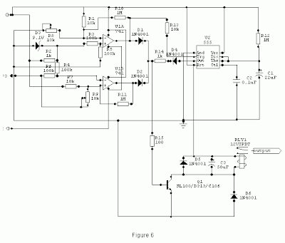
Build a High And Low Voltage Cut Off With Time Delay Circuit Diagrams
The under/over voltage protection circuit with time delay presented here is a low cost and reliable circuit for protecting such equipments from damages. Whenever the power line is switched on it gets connected to the appliance only after a delay of a fixed time. If there is hi/low fluctuations beyond sets limits the appliance get disconnected. The system tries to connect the power back after the specific time delay, the delay being counted from the time of disconnection. If the power down time (time for which the voltage is beyond limits) is less than the delay time, the power resumes after the delay: If it is equal or more, then the power resumes directly.
This circuit has been designed, built and evaluated by me to use as a protector for my home refrigerator. This is designed around readily available semi-conductor devices such as standard bipolar medium power NPN transistor (D313/SL100/C1061), an 8-pin type 741 op-amp and NE555 timer IC. Its salient feature is that no relay hunting is employed. This draw back is commonly found in the proctors available in the market.
The complete circuit is consisting of various stages. They are: - Dual rail power supply, Reference voltage source, Voltage comparators for hi/low cut offs, Time delay stage and Relay driver stage. Lets now look at the step-by-step design details.
This is a conventional type of power supply as shown in Figure 1. The power is applied through the step-down transformer (230/12-0-12V/500mA). The DC proportional to the charging input voltage is obtained from bridge rectifier. Two electrolytics are there to bypass any spikes present. Bridge is capable of handling currents up to 1 Amp.
Output is given by: -
V(out) = 0.71 X V (secondary)
= 0.71 X 24V
= 17.04 V
(This equation is similar for the negative rail as well)
Figure 2 shows the use of very common and easily available op-amp 741 as a comparator. The op-amp is available in TO-5 and DIP type packing.
When the sensor input is less than Zener voltage the output from the Op-amp remains high and when it is greater than Zener voltage the output goes low. When the sensing voltage is equal to Zener voltage the output of the op-amp is approximately zero.
This phenomenon is used as a decision for switching the relay and to give cutoff in a low voltage situation.
Here the op-amp is used as a inverted amplifier. See Figure 3.Zener and resistor network gives reference voltage to the inverting terminal (-ve) of op-amp. Sensing voltage derived through the 10 K pre-set is given to the non- inverting (+ve) terminal and this sets the high level cut.
When the input DC from the sensor is less than Zener voltage the output of the op-amp is low and vice-versa. When the input DC voltage is equal to the zener voltage, the op-amps output is approximately zero.
I’ve selected the 555 timer due to following reasons.
1. Timing from microseconds through hours.
2. Ability to operate from wide range of supply voltages.
3. High temperature stability.
4. Easily Available.
5. Its triggering circuit is quite sensitive.
This is basically a monostable. The external timing capacitor C2 is held initially discharged by the timer. The circuit triggers upon receiving a pulse to its pin 2 when the level reaches 1/3 Vcc. Once triggered., the circuit will remain in that state until the set time is elapsed or power to the circuit cuts off. The delayed period in seconds is 1.1 C2.R1 where R1 is in megohms and C2 is in microfarads. In practice, R1 should not exceed 20 M. If you use an electrolytic capacitor for C2, select a unit for low leakage. The time delay may have to be adjusted by varying R1 to compensate for the wide tolerance of electrolytics.
Circuit diagram
The output from the voltage level detectors cannot directly drive the relay and hence the relay driver is used.
Generally in a relay driver circuit, parallel to the relay coil, a diode or a capacitor is used. This is to eliminate the back e.m.f generated by the relay coil when currents are suddenly broken. Capacitor C1 is connected in parallel to the coil, which filters out the back emf but it, slows down the working of relay.
A better method is to connect two diodes (as shown in the figure 5) that stop the relay – transistor junction swinging more than 600mV above the positive rail or below the zero-volt rail. During normal operation the diodes are reverse biased and have no effect on the performance of circuit. But when back emf is induced, the diodes conduct heavily and absorb all transient voltages. However, I have employed the both methods.
When the input voltage is below or above the limits set by the pre-sets R8 or R9, the output of the Op-Amps goes either low or high and diodes D1 or D2 would be forward biased depending on the situation. Transistor Q1 switches ON and the flow of current from collector to emitter energizes the relay and the output is cutoff.
A small amount of hystersis has been added via feed back resistors R10 & R11 so that the relay turns on when the level falls to a particular value but does not turn again until it raises a substantial amount above this value. Other wise the relay contacts will frequently turn on/off and produce chattering.
1) I used a piece of varoboard, which has copper strips on one side to mount the components, and housed the entire circuit and the transformer in a discarded ATX PC power supply box.
2) An autotransformer has been used to set the limits. Set the output of the autotransformer to 250V AC and connect it to the primary of transformer T1 (see Figure 1). Then adjust the pre-set R9 such that relay just energizes. This is the high limit. Next set the output of the autotransformer to 200V AC and adjust the pre-set R8 such that the relay energizes. Please note that these are my preferred limits but you may select any range from say 170 to 270V AC.
3) A neon with a suitable resistor could be connected between the AC supply lines as an ON indicator. Alternatively, LED with a current limiting resistor could be connected between the relay coil so when the relay is energized LED will indicate the situation.
Thursday, December 19, 2013
Proximity Switch
For example, if a tin foil sensor is mounted underneath a table, metal items on top of the table, such as cutlery, or a dinner service, become sensors themselves. The touch plate connected to the free end of R1 detects the electric field surrounding the human body, and this is of a relatively constant value and can therefore be reliably picked up. R1 is not strictly necessary, but serves as some measure of protection against static charge on the body if the sensor should be touched directly. As a body approaches the sensor, the value of C1 effectively increases, causing the frequency of oscillator IC1.A to drop.
Consequently capacitor C2 has more time to discharge through P2, with the result that the inputs at IC1.B go Low, and the output goes High. As the output goes High, so C3 is charged through LED D2. D2 serves a dual purpose —namely as a visual indication of detection, and to lower the maximum charge on C3, thus facilitating a sharper distinction between High and Low states of capacitor C3. The value of R4 is chosen to enable C3 to discharge relatively quickly as pulses through D2 are no longer sufficient to maintain its charge. The value of C3 may be increased for a longer sounding of the siren, with a slight reduction in responsiveness at the sensor.
When C3 goes High, this triggers siren IC1.C and IC1.D. The two NAND gates drive piezo sounder X1 in push-pull fashion, thereby greatly increasing its volume. If a piezo tweeter is used here, the volume will be sufficient to make one’s ears sing. The current consumption of the circuit is so low a small 9-V alkaline PP3 battery would last for about one month. As battery voltage falls, so sensitivity drops off slightly, with the result that P1 may require occasional readjustment to maintain maximum sensitivity. On the down side of low cost, the hysteresis properties of the 4093 used in the circuit are critical to operation, adjustment and stability of the detector.
In some cases, particularly with extremely high sensitivity settings, it will be found that the circuit is best powered from a regulated voltage source. The PCB has an extra ground terminal to enable it to be easily connected to a large earthing system. Current consumption was measured at 3.5 mA stand-by or 7 mA with the buzzer activated. Usually, only P1 will require adjustment. P2 is used in place of a standard resistor in order to match temperature coefficients, and thus to enhance stability. P2 should be adjusted to around 50 k, and left that that setting.
The circuit is ideally adjusted so that D2 ceases to light when no body is near the sensor. Multiturn presets must be used for P1 and P2. Since the piezo sounder is the part of the circuit which is least affected by body presence, a switch may be inserted in one of its leads to switch the alarm on and off after D2 has been used to check adjustment. Make sure that there is a secure connection between the circuit and any metal sensor which is used.
Resistors:
- R1 = 10kΩ
- R2 = 4kΩ7
- R3 = 1kΩ
- R4 = 47kΩ
- R5 = 47kΩ
- P1,P2 = 100kΩ multiturn cermet, horizontal
- C1,C2 = 22pF
- C3 = 22µF 40V radial
- C4 = 10nF
- C5 = 100µF 25V radial
- D1 = 1N4148
- D2 = LED, red
- IC1 = 4093
- BZ1 = AC buzzer
Wednesday, December 18, 2013
Operational Amplifier Op Amp Basics
Operational Amplifier (Op-Amp) Basics |
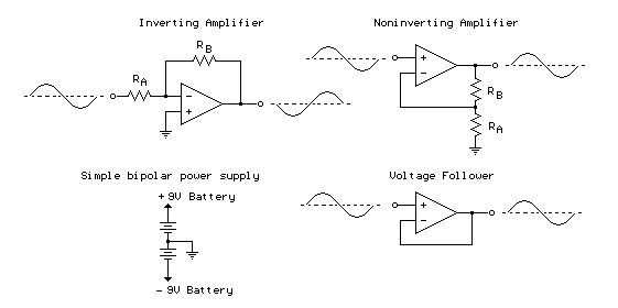
Inverting Amplifier:
The op-amp is connected using two resistors RA and RB such that the input signal is applied in series with RA and the output is connected back to the inverting input through RB. The non-inverting input is connected to the ground reference or the center tap of the dual polarity power supply. In operation, as the input signal moves positive, the output will move negative and visa versa. The amount of voltage change at the output relative to the input depends on the ratio of the two resistors RA and RB.
As the input moves in one direction, the output will move in the opposite direction, so that the voltage at the inverting input remains constant or zero volts in this case. If RA is 1K and RB is 10K and the input is +1 volt then there will be 1 mA of current flowing through RA and the output will have to move to -10 volts to supply the same current through RB and keep the voltage at the inverting input at zero. The voltage gain in this case would be RB/RA or 10K/1K = 10. Note that since the voltage at the inverting input is always zero, the input signal will see a input impedance equal to RA, or 1K in this case. For higher input impedance, both resistor values can be increased.
Non-inverting Amplifier:
The non-inverting amplifier is connected so that the input signal goes directly to the non-inverting input (+) and the input resistor RA is grounded. In this configuration, the input impedance as seen by the signal is much greater since the input will be following the applied signal and not held constant by the feedback current. As the signal moves in either direction, the output will follow in phase to maintain the inverting input at the same voltage as the input (+). The voltage gain is always more than 1 and can be worked out from Vgain = (1+ RB/RA).
Voltage Follower:
The voltage follower, also called a buffer, provides a high input impedance, a low output impedance, and unity gain. As the input voltage changes, the output and inverting input will change by an equal amount.
- Source
- Bowdens Hobby Circuits
Tuesday, December 17, 2013
Belgian Earth Fault Detector
Monday, December 16, 2013
Home Made Metal Detector
Normally, the center frequency of the voltage controlled oscillator (VCO) from the PLL loop that is contained in IC1 is equal to the oscillation frequency of T1. This changes when entering a metallic object (ferrous or nonferrous) in the field induced by L1. S1 is a miniature 2-pole switch. Meter needle deviation is a measure of frequency change, since the direction of deviation depends on the type of material detected by the coil. The meter tool used for this homemade metal detector is zero as central, +-50µA.
Metal detector circuit schematic
Coil L1 consists of 40 turns of enamelled copper wire, wound on a plastic template with a diameter of about 10 cm. Inductance thus obtained ensure the functioning of the oscillator at a frequency approximately equal to the VCO included in the PLL loop. Use an oscilloscope to check that pin 2 of IC1 delivers sinusoidal signal with frequency about 75 kHz.
Adjust P1 so that fronts rectangular signal from pin 4 to coincide with the peaks of the sinusoidal signal from pin 2. Then, adjust P2 in order to obtain 0 on the meter. Since the neutral zero setting “runs” with the battery’s decreasing voltage it will be necessary to restore it (zero balancing) from time to time during use of the metal detector.
Wednesday, October 9, 2013
Bar Mode Lights Sequencer
This circuit, designed on request, allows up to 15 LED clusters to illuminate in bar-mode sequence. LED sequencing will start at power-on and, after reaching the desired output, all the LEDs turn off and sequence restarts. The number of LEDs or clusters forming the bar can be selected by connecting R7 to the appropriate output pin of IC2 or IC3.
Parts:
R1,R5,R9_________1K 1/4W Resistors
R2______________33K 1/4W Resistor
R3_____________100K 1/2W Trimmer Cermet
R4_______________1M 1/4W Resistor
R6,R10__________10K 1/4W Resistors
R7,R8___________22K 1/4W Resistors
R11______________4K7 1/4W Resistor
R12_____________33R 1/4W Resistor (See Notes)
C1______________10µF 25V Electrolytic Capacitor
C2_____________100nF 63V Polyester Capacitor
C3_____________470µF 25V Electrolytic Capacitor
D1--D14________LEDs (See Notes)
Q1___________2N3819 General-purpose N-Channel FET
Q2,Q3,Q5______BC547 45V 100mA NPN Transistors
Q4____________BC337 45V 800mA NPN Transistor
IC1____________7555 or TS555CN CMos Timer IC
IC2,IC3________4094 8-stage shift-and-store bus register IC
Notes:
- R5 and D1 are optional: they could be of some utility in monitoring the sequence frequency set by means of R3.
- The terminal of R7 bearing an arrow must be connected to the desired output pin of IC2 or IC3 in order to select the number of LEDs or clusters forming the bar.
- For example: if you want to drive seven LEDs or clusters connect R7 to pin#11 of IC2 (Output 8) and the LED or cluster drivers to Outputs 1 to 7 respectively.
- Clusters can be formed by up to 12 LEDs as shown in the circuit diagram, right side. Common cluster types usually range from 5 to 10 LEDs.
- Up to 15 of these cluster driver circuits, each formed by the LEDs, two transistors and three resistors can be built and connected to the progressively numbered outputs of IC2 (the first eight clusters) and IC3 (the remaining clusters).
- If a number of clusters up to 7 is required, IC3 can be omitted.
- Constant output current value for the LEDs can be changed by varying R10.
- The formula is: R = 0.6/I (I expressed in Amperes).
- Wanting to drive only one LED per output instead of a cluster, the above mentioned cluster driver can be substituted by a single transistor, as shown in the circuit formed by D2, Q3, R8 and R9.
Tuesday, October 8, 2013
Dimmer With A MOSFET
R1 is intended as protection for the LED in the optocoupler. R1 also functions as a normal current limiting device so that a ‘hard’ voltage can be applied safely. The optocoupler is anold acquaintance, the CNY65, which provides class-II isolation. This ensures the safety of the regulator. The transistor in the optocoupler is connected to the positive power supply so that T1 can be brought into conduction as quickly as possible. In order to reduce switching spikes as a consequence of parasitic inductance, the value of R2 has been selected to be not too low: 22 kΩ is a compromise between inductive voltages and switching loss when going into and out of conduction.
An additional effect is that T1 will conduct a little longer than what may be expected from the PWM signal only. When the voltage across T1 reduces, the voltage across D1 remains equal to 10 V up to a duty cycle of 88 %. A higher duty cycle results in a lower voltage. At 94 % the voltage of 4.8 V proved to be just enough to cause T1 to conduct sufficiently. This value may be considered the maximum duty cycle. At this value the transistor is just about 100 % in conduction. At 230 V mains voltage, the voltage across the lamp is only 2.5 V lower, measured with a 100-W lamp. Just to be clear, note that this circuit cannot be used to control inductive loads. T1 is switched asynchronously with the mains frequency and this can cause DC current to flow.
Electronic lamps, such as the PL types, cannot be dimmed with this circuit either. These lamps use a rectifier and internally they actually operate off DC.A few remarks about the size of R3 and R4. This is a compromise between the lowest possible current consumption (when the lamp is off) and the highest possible duty cycle that is allowed. When the duty cycle is zero, the voltage across the resistors is at maximum, around 128 V with a mains voltage of 230 V. Because (depending on the actual resistor) the voltage rating of the resistor may be less than 300 V, two resistors are connected in series. The power that each resistor dissipates amounts to a maximum of 0.5W. With an eye on the life expectancy, it would be wise to use two 1-W rated resistors here.
Monday, October 7, 2013
10 to 1000 MHz Oscillator
Connecting the feedback capacitors C1 and C2 to pins 3 (FDBK) and 4 (VTUNE) transforms the internal transistor into a Colpitts oscillator. A resonator is also needed; here this consists of C4 and L1, and it is coupled via C3. Keep the Q factor of the coil as high as possible (by using an air-core coil, for example), to ensure a low level of phase noise. Since most applications require a tuneable oscillator, the varicap diode D1 (BBY40, BBY51, BB804 etc) can be used to adjust the resonant frequency. The tuning voltage UTune is applied via a high resistance. The value of the tuning voltage naturally depends on the desired frequency range and the variable-capacitance diode (D1) that is used. The table shows a number of suggestions for selecting the frequency-determining components. If the frequency range is narrow, a parallel-resonant circuit should be connected between the output pin and +Vcc, to form the collector load for the output transistor.
This can be built using the same components as the oscillator resonator. With a broadband VCO, use a HF choke instead, with a value of a few microhenries to a few nanohenries, depending on the frequency band. In this case C6 is not needed. The output level of this circuit is –3dBm with an LC load and –7 dBm with a choke load. The table that accompanies the schematic diagram provides rough indications of component values for various frequencies. It is intended to provide a starting point for experimentation. The coupling between the variable-capacitance diode and C5 determines the tuning range of the VCO. The manufacturer maintains an Internet site at www.rfmd.com, where you can find more information about this interesting oscillator IC.
Sunday, October 6, 2013
Video Tracer For Trouble Shooting
Another use for the buzzer option is to provide a video fault indication. For example, it could be inserted in bridging mode, with switch S1 in high impedance mode (position 2) across a video line and set to alarm when there is no video present. If someone pulls out a cable or the video source is powered off, the alarm would sound. IC1 is a standard LM1881 video sync separator circuit and 75Ω termination can be switched in or out with switch S1a. The other pole of the switch, S1b, turns on the power. The composite sync output at pin 1 is low with no video input and it pulses high when composite sync is detected.
These pulses charge a 100nF capacitor via diode D1. When there is no video at the input, oscillator IC2b is enabled and provides a short pulse every couple of seconds to flash the LED. The duty cycle is altered by including D2, so that the discharge time for the 10μF capacitor is much shorter than the charge time. The short LED pulse is used as a power-on indicator drawing minimal average current. When video is present at the input, IC2b is disabled and IC2d is enabled. The output of IC2d provides a 10Hz square wave signal to flash the LED. The buzzer is controlled by switch S2. In position 2 the buzzer will sound when there is video at the input and in position 1 the buzzer will sound when there is no video at the input.
Saturday, October 5, 2013
CAPACITANCE METER ELECTRONIC DIAGRAM
Friday, October 4, 2013
Step Up Booster Powers Eight White LEDs
The constant-current design of the circuit guarantees a steady current through all LEDs, regardless of the forward voltage differences between them. Although this circuit was designed to operate from a single Li-Ion battery (2.5V to 4.5V), the LT1615 is also capable of operating from inputs as low as 1 V with relevant output power reductions. The Motorola MBR0520 surface mount Schottky diode (0.5 A 20 V) is a good choice for D1 if the output voltage does not exceed 20 V. In this application however, it is better to use a diode that can withstand higher voltages like the MBR0540 (0.5 A, 40 V). Schottky diodes, with their low forward voltage drop and fast switching speed, are the best match.
Many different manufacturers make equivalent parts, but make sure that the component is rated to handle at least 0.35 A. Inductor L1, a 4.7-µH choke, is available from Murata, Sumida, Coilcraft, etc. In order to maintain the constant off-time (0.4 ms) control scheme of the LT1615, the on-chip power switch is turned off only after the 350-mA (or 100-mA for the LT1615-1) current limit is reached. There is a 100-ns delay between the time when the current limit is reached and when the switch actually turns off. During this delay, the inductor current exceeds the current limit by a small amount. This current overshoot can be beneficial as it helps increase the amount of available output current for smaller inductor values.
Thursday, October 3, 2013
1W BTL Audio Amplifier Circuit Diagram
Wednesday, October 2, 2013
Soldering Iron Tip Preserver
Oxidisation is then negligible and the iron can be brought back up to soldering temperature in just a few seconds when needed. In addition, normal soldering operation, where the iron is returned to rest only momentarily, is unaffected because of the thermal inertia of the iron. Two 555 timers (IC1 & IC2) form the heart of the circuit. IC1 is wired as a monostable and provides an initial warm-up time of about 45 seconds to bring the iron up to temperature. At the end of this period, its pin 3 output switches high and IC2 (which is wired in astable configuration) switches the iron on - via relay RLY1 - for about one second in six to maintain the standby temperature.
The presence of the iron in its stand is sensed by electrical contact between the two and some slight modification of the stand may be necessary to achieve this. When the iron is at rest, Q1s base is pulled low and so Q1 is off. Conversely, when the iron is out of its stand, Q1 turns on and pulls pins 2 & 6 of IC2 high, to inhibit its operation. During this time, pin 3 of IC2 is low and so the iron is continuously powered via RLY1s normally closed (NC) contacts. Note that the particular soldering iron that the circuit was designed for has its own 24V supply transformer. Other irons may need different power supply arrangements. The warm-up time and standby temperature can be varied by altering R2 and R5, as necessary.
Tuesday, October 1, 2013
Power Buzzer
The frequency of the tone can also be adjusted using P1. There is no volume control, since you always want to get attention when you press push-button S1. Fit the entire circuit where you want to have the push-button. The loudspeaker can then be placed in a strategic location, such as in the bedroom or wherever is appropriate. Use speaker cable to connect the loudspeaker. Normal bell wire can cause a significant power loss if the loudspeaker is relatively far away. The loudspeaker must be able to handle a continuous power of at least 6 W (with a 20-V supply voltage).
The power quickly drops as the supply voltage decreases (P = Urms 2 / RL). The power supply for this circuit is not particularly critical. However, it must be able to provide sufficient current. A good nominal value is around 400 mA at 20 V. At 4 V, it will be approximately 25 mA. Most likely, you can find a suitable power supply somewhere in your hobby room. Otherwise, you can certainly find a low-cost power supply design in our circuits archive that will fill the bill!
Monday, September 30, 2013
SAFELY DISCHARGE X CAPACITORS ELECTRONIC DIAGRAM
When the AC voltage is disconnected, CAPZero automatically and safely discharges the X capacitor by closing the circuit through the bleed resistors and directing the energy away from the exposed AC plug. This approach provides engineers with total flexibility in their choice of the X capacitor used to optimize differential- mode EMI filtering without worrying about the effect of the required bleed resistors on system no-load and standby power budget. The innovative design inherently meets international safety standards for all open and short-circuit fault tests, allowing CAPZero to be used before or after the system input fuse. CAPZero is suitable for all AC-DC converters with X capacitors that require very low standby power. It’s offered with 825- or 1,000-V MOSFETs to support a variety of power supply design needs. It is ideal for a wide range of applications, including PCs, servers/workstations, monitors and TVs, printers and notebooks, and appliances requiring EuP Lot 6 compliance and adapters requiring ultra-low no-load consumption. CAPZero devices are available now in an SO-8 package at $0.40 each for 10,000- piece quantities. [www.powerint.com]
Sunday, September 29, 2013
5V DC REGULATED PHONE CHARGER ELECTRONIC DIAGRAM
Regulated phone charger which is used as an emergency charger for mobile phones with source from ordinary batteries, and works with 1.5V input DC voltage. At 5V, it can provide output to 70mA. If the current is drawn, the voltage will be drop. A006 microcontroller is used to create square wave which used to drive the Field Effect Transistor BBV93.
Saturday, September 28, 2013
Flickering Light II
UJTs are suitable for use as pulse generators, monostable multivibrators, trigger elements and pulse-width modulators. If a positive voltage is applied to the emitter (E), the capacitor charges via the resistor. As soon as the voltage on the emitter reaches approximately half the supply voltage (for a 2N2645, the value lies in the range of 56–75 %), the UJT ‘fires’ and the capacitor discharges via base B1 and the resistor, generating a positive pulse. The UJT then returns to the non-conduct state, and the process just described repeats periodically. The frequency can be approximately given by the formula f ˜ 1/(RC) The frequency is independent of the value of the supply voltage (which must not exceed 35 V).
The maximum emitter blocking voltage is 30 V, and the maximum permissible emitter current is 50 mA. The values of resistors R1, R2 and R3 can lie between 3 k? and 500 k?. If necessary, the frequency can be varied over a range of 100:1 by using a trimpot instead of a fixed resistor. The frequencies from the three pulse generators are mixed by connecting them to the IR diode of a triac optocoupler via R4. The optocoupler, a type MOC3020, K3030P or MCP3020, can handle a maximum load current of 100mA. The triac triggers at irregular intervals and generates the desired flickering light in the two small lamps, L1 and L2, which are connected in series to the transformer secondary.
The light effect can be noticeably improved by using a MOC3040, which contains a zero-voltage switch, since its generates irregular pauses of various lengths when suitable frequencies occur in the individual oscillators. The zero-voltage switch does not switch while the current is flowing, but only when the applied ac voltage passes through zero. An integrated drive circuit (zero crossing unit) allows full half-waves or full cycles to pass (pulse-burst control) Due to the flickering effect arising from its switching behaviour, it is not suitable for normal lighting, but here this just what we want. This version of the optocoupler is also designed for a maximum current of 100 mA.
For a small roof fire or the light of a welding torch in a workshop, two small incandescent lamps connected in series and rated at 6 V / 0.6 A (bicycle taillight bulbs) or a single 12-V lamp (rated at 100 mA) is adequate. If it is desired to simulate a large fire, a triac (TIC206D, rated at 400 V / 4 A, with a trigger current of 5 mA) can be connected to the output of the circuit and used to control a more powerful incandescent lamp. As continuous flickering looses its attraction for an interested observer after a while (since no house burns for ever, and welders also take breaks), it’s a good idea to vary the on and off times of the circuit. This is handled by a bipolar Hall switch (TLE4935L), which has such a small package that it can fitted between the sleepers of all model railway gauges, including Miniclub (Z Gauge), or even placed alongside the track if a strong permanent magnet is used.
If a magnet is fixed somewhere on the base of a locomotive such that the south pole points toward the package of the Hall switch (the flattened front face with the type marking), the integrated npn transistor will switch on and pull the base of the external pnp transistor negative, causing the collector–emitter junction to conduct and provide the necessary ‘juice’ for the unijunction transistors. If another traction unit whose magnet has it s north pole pointing toward the Hall switch passes a while later, the switch will be cut off and the flickering light will go out. Of course, you can also do without this form of triggering and operate the device manually.
Friday, September 27, 2013
A 12V Car Charger For ASUS Eee Notebook
- 2x 10k resistor (R1 & R4)
- 2x 22k resistor (R2 & R3)
- 1x 1.5k resistor (R5)
- 1x 120μF 25v electrolytic capacitor (C1)
- 1x 2200μF 16v electrolytic capacitor (C2)
- 1x 1N5822 Schottky diode (or equivalent)
- 1x 9.1v 0.5W Zener diode
- 1x BC337 NPN transistor
- 1x LM2576T-ADJ IC
- 1x 100uH, 3A inductor (e.g. Pulse PE92108KNL)
- 25°C/W or better minature heatsink (e.g. Thermalloy 6073)
- Cigarette lighter plug with 3A fuse and 2.1mm DC plug (e.g. DSE P1692)
- 2.1mm DC chassis mount socket
- 1.7mm x 4.75mm (ID x OD) DC plug and cable
- Small plastic enclosure
Thursday, September 26, 2013
Automatic Air Humidifier
It is also transformed to a 7.5 V supply voltage by D2 and C2. The sensor needs an alternating drive voltage at a level not higher than 1.5 V. This potential is obtained from the pulsating direct voltage by network R2-R3-C3-C4, which removes the direct voltage component and lowers the level to 1.4 V. At the same time, the network functions as a 50 Hz bandpass filter. To ensure that the drive voltage for the sensor does not fall outside the common-mode range of op amp IC2, an offset potential of 3.9 V is applied to the sensor as well as to the voltage reference source of the op amp.
This potential is provided by zener diode D3. The reference level is set with P1.The op amp is given some hysteresis by R5. When the humidity of the ambient air rises above that corresponding to the level with P1, the output voltage of IC2 is about 6 V. This results in T1 being cut off by D4, whereupon the triac is also disabled. When the humidity drops below that corresponding to the level set with P1, a pulsating potential appears at the output of IC2. This voltage is used to charge capacitor C6.
The charged capacitor thereupon provides a steady current to the triac. When T1 is cut off for some time, capacitor C6 is discharged via resistor R7. Capacitors C1 and C7 are discharged via R9, so that after the mains has been switched off, no dangerous potential remains at the pins of the mains connector (K1). The humidifier is best built on the PCB shown in Figure 2, which is available ready made (see Readers services pages towards the end of this issue). Bear in mind that parts of the board will carry mains voltage, which makes careful working and the enclosing of the board in a plastic case imperative. The humidifier may be converted into a dehumidifier by interchanging connections 1 and 3 to sensor IC1.
Parts list
Resistors:
R1 = 470 Ω, 1 W
R2, R3 = 10 kΩ
R4 = 1 kΩ
R5 = 56 kΩ
R6 = 6.8 kΩ
R7 = 4.7 kΩ
R8 = 470 Ω
R9 = 2.2 MΩ
R10 = 39 Ω, 1 W
P1 = 1 kΩ preset
Capacitors:
C1 = 0.47 µF, 250 V a.c.
C2 = 470 µF, 16 V, radial
C3, C4 = 0.33 µF, metallized polyester, 5%
C5 = 0.1 µF, high stability
C6 = 47 µF, 16 V, radial
C7 = 0.047 µF, 250 V a.c.
Semiconductors:
D1 = zener diode, 8.2 V, 1.3 W
D2 = 1N4001
D3 = zener diode, 3.9 V, 500 mW
D4 = zener diode, 2.4 V, 500 mW
T1 = BC557B
Integrated circuits:
IC1 = NH-3 (Figaro)
IC2 = TLC271CP Tri
1 = TLC336T (SGS)
Miscellaneous:
K1, K2 = 2-way terminal block for board mounting, pitch 7.5 mm
F1 = fuse-holder with 630 mA slow fuse